Mechanical structure of vacuum aluminum brazing furnace
In order to better explain the electrical control system, the mechanical structure of this type of vacuum aluminum brazing furnace is first introduced, as shown in Figure 1. The main body of the vacuum aluminum brazing furnace is composed of a heating chamber, a furnace body, a front and back stove door and various functional parts. The heating chamber is installed in the furnace body and consists of a plurality of heating resistors and insulation layers. The heating resistors are connected by the electrodes and cables outside the furnace body to form 28 heating zones. Each zone is powered by a set of thyristor voltage regulating power supply circuit. The furnace body is a double-layer water-cooled jacket structure with the necessary functional components of brazing furnace welded on it. The front and rear doors are also double-layer water-cooled jacket structure, which can be mounted on the door car which can move vertically along the axis of the furnace body. The door can also be moved horizontally along the axis of the furnace body by the cylinder driving on the door car. The translation of the two directions of the door enables the door to open. And close.
The peripheral system of vacuum brazing furnace includes vacuum system, water cooling system, gas charging system, pneumatic system and charging car outside furnace.
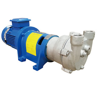
Aluminum alloy brazing requires a very high vacuum system. The vacuum system should not only have strong enough vacuum acquisition capacity, but also have sufficient capacity to ensure that the vacuum degree in the furnace is kept at 10-3Pa order of magnitude when a large amount of gas evaporates during the pre-brazing and final brazing stages. Speed up. The vacuum brazing furnace is equipped with 5 sets of vacuum units, each set of vacuum unit configuration: the main pump is a high vacuum oil diffusion pump, oil diffusion pump is a kind of steam jet pump, it has the advantages of high pumping speed, high vacuum limit: the role of mechanical pump unit is pre-pumping vacuum and as a diffusion pump of the front pump, it is by Roots pump And slide valve pump composition: maintenance pump using rotary vane pump, it can ensure that the equipment starts to work before the diffusion pump pre-heating pump chamber to maintain a certain degree of vacuum, but also ensure that after the completion of work in the diffusion pump cooling process, in order to save energy and shut down Roots pump and slide valve pump, diffusion pump will not appear when the oil oxidation; The valves of each vacuum unit include large valves, front valves, pre draining valves and unit bleeder valves. The water cooling system is used to cool the brazing furnace wall, diffusion pump, roots pump, slide valve pump and rotary vane pump. The main intake pipe installs the electric contact pressure gauge, and alarm when the water supply pressure is insufficient. The water flows through the cooling component to the return channel, and the return channel is connected with the main return pipe. The device has an inert gas inflatable interface and equipped with manual ball valves and manual needle valves. According to the need, nitrogen replacement can be realized in the pre vacuum pumping stage.
The equipment is equipped with pneumatic system. The system is composed of air source triple parts, pipelines, seals and other components. The pneumatic system pipeline can withstand pressure of 0.8-1 MPa. It is used for components driven by cylinders on the equipment, including large valves, front-stage valves, pre-suction valves and front and rear furnace doors. Workpiece truck is used to load and unload workpieces. Its main body is the frame. The size of the frame matches the maximum size of the workpiece after loading and unloading. The structure strength is enough to bear the total mass of the load. The track fixed on the ground is used to support the frame and guide the movement of the frame. The advance and retreat of the frame are driven by a reduction motor (power 2.2kW) fixed in the pit. The frame moves toward the furnace body to realize the docking of the guide rail on the frame and the square section guide rail in the heating chamber. The other group is fixed on the frame to reduce the speed. The motor (power is 2.2kW) drives the workpiece trailer which can move along the guide rail to move forward and backward, so that the workpiece moving with the roller assembly moves in and out along the furnace and the guide rail on the frame to realize the loading and unloading process. The movement of the frame and the entry and exit of the workpiece have the limit of the travel switch, which realizes the accurate docking of the guide rail and the arrival and exit of the workpiece.
Related products:


评论
发表评论